


Electrical Fundamentals
*Reproduced with permission from Leeson
Rating Parameters
Voltage
Common 60hz voltages for single-phase motors are 115 volt, 230 volt, and 115/230 volt.
Common 60hz voltages for three-phase motors are 230 volt, 460 volt and 230/460 volt. Two hundred volt and 575 volt motors are sometimes encountered. In prior NEMA standards these voltages were listed as 208 or 220/440 or 550 volts. Motors with these voltages on the nameplate can safely be replaced by motors having the current standard marking of 200 or 208-230/460 or 575 volts, respectively.
Motors rated 115/208-230 volt and 208-230/460 volt, in most cases will operate satisfactorily at 208 volts, but the torque will be 20% - 25% lower. Operating below 208 volts may require a 208 volt (or 200 volt) motor or the use of the next higher horsepower, standard voltage motor.
Current (Amps)
In comparing motor types, the full load amps and/or service factor amps are key parameters for determining the proper loading on the motor. For example, never replace a PSC type motor with shaded pole type as the latter's will not normally be 50% - 60% higher. Compare PSC with PSC, capacitor start, and so forth.
HORSEPOWER
Exactly 746 watts of electrical power will produce 1 HP if a motor could operate at 100% efficiency, but of course no motor is 100% efficient. A 1 HP motor operating at 84% efficiency will have a total watt consumption of 888 watts. This amounts to 746 watts of usable power and 142 watts loss due to heat, friction, etc. (888 x .84 = 746 = 1 HP).
Horsepower can also be calculated if torque is known, using one of these formulas:
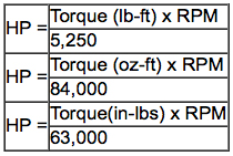
Torque:
The turning effort or force applied to a shaft, usually expressed in inch-pounds or inch-ounces for fractional or sub-fractional HP motors.
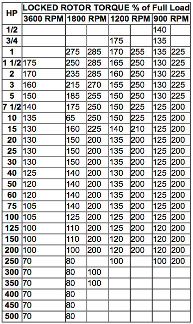
Starting Torque:
Force produced by a motor as it begins to turn from standstill and accelerate (sometimes called locked rotor torque).
Full Load Torque:
The force produced by a motor running at rated full-load speed at rated horsepower.
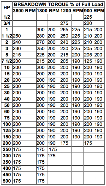
Breakdown Torque:
The maximum torque a motor will develop under increasing load conditions without an abrupt drop in speed and power (sometimes called pull-out torque).
Pull-Up Torque:
The minimum torque delivered by a motor between zero and the rated RPM, equal to the maximum load a motor can accelerate to rated RPM.
NEMA Locked Rotor:
For three phase motors, 60Hz & 50Hz at rated voltage. (Design B torques in black; Design C torques in blue)
Breakdown: For three phase motors, 60Hz & 50Hz at rated voltage.
Speeds:
The approximate RPM at rated load for small and medium motors operating at 60 hz and 50 hz at rated volts are as follows:
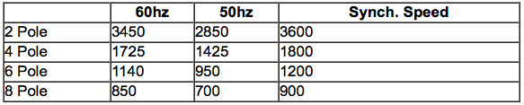
Synchronous speed (no-load) can be determined by this formula:
Frequency (hertz) x 120 / Number of Poles
Insulation Class
Insulation systems are rated by standard NEMA classifications according to maximum allowable operating temperatures. They are as follows:
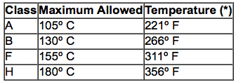
Generally, replace a motor with one having an equal or higher insulation class. Replacement with one of lower temperature rating could result in premature failure of the motor. Each 10° C rise above these ratings can reduce the motor's service life by one half.
Service Factor
The service factor (SF) is a measure of continuous overload capacity at which a motor can operate without overload or damage, provided the other design parameters such as rated voltage, frequency and ambient temperature are within norms. Example: a 3/4 HP motor with a 1.15 SF can operate at .86 HP, (.75 HP x 1.15 = 862 HP) without overheating or otherwise damaging the motor if rated voltage and frequency are supplied at the motor's leads. Some motors, including most LEESON motors, have higher service factors than the NEMA standard.
It is not uncommon for the original equipment manufacturer (OEM) to load the motor to its maximum load capability (service factor). For this reason, do not replace a motor with one of the same nameplate horsepower but with a lower service factor. Always make certain that the replacement motor has a maximum HP rating (rated HP x SF) equal to or higher than that which it replaces. Multiply the horsepower by the service factor for determining maximum potential loading.
For easy reference, standard NEMA service factors for various horsepower motors and motor speeds are shown in this table.
NEMA Service Factor at Synchronous Speed (RPM) FOR DRIP PROOF MOTORS:
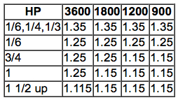
The NEMA standard service factor for totally enclosed motors is 1.0. However, many manufacturers build TEFC motors with 1.15 service factors.
Capacitors
Capacitors are used on single-phase induction motors except shaded-pole, split-phase and polyphase. Start capacitors are designed to stay in circuit a very short time (3-5 seconds), while run capacitance are permanently in circuit. Capacitors are rated by capacitance and voltage. Never use a capacitor with lower capacitance or voltage ratings for replacement. A higher voltage is acceptable.
Efficiency
A motor's efficiency is a measurement of useful work produced by the motor versus the energy that it consumes (heat and friction). An 84% efficient motor with a total watt draw of 400W produces 336 watts of useful energy (400 x .84 = .336W). The 64 watts lost (400 - 336 = 64W) becomes heat.
Thermal Protection
Thermal Protection (overload)
A thermal protector, automatic or manual, mounted in the end frame or on a winding, is designed to prevent a motor from getting too hot, causing possible fire or damage to the motor. Protectors are generally current and temperature sensitive. Some motors have no inherent protector, but they should have protection provided in the overall system's design for safety. Never bypass a protector because of nuisance tripping. This is generally an indication of some other problem, such as overloading or lack of proper ventilation. Never replace nor choose an automatic-reset thermal overload protected motor for an application where the driven load could cause personal injury if the motor should restart unexpectedly. Only manual-reset thermal overloads should be used in such applications.
Basic types of overload protectors include:
Automatic Reset: After the motor cools, this line-interrupting protector automatically restores power. It should not be used where unexpected restarting would be hazardous.
Manual Reset: This line-interrupting protector has an external button that must be pushed to restore power to the motor. Use where unexpected restarting would be hazardous, as on saws, conveyors, compressors and other machinery.
Resistance Temperature Detectors: Precision-calibrated resistors are mounted in the motor and are used in conjunction with an instrument supplied by the customer to detect high temperatures.
Circuit Wiring
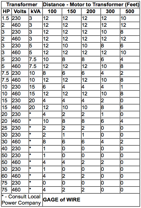
All wiring and electrical connections should comply with the National Electrical Code (NEC) and with local codes and practices. Undersized wire between the motor and the power source will limit the starting and load carrying abilities of the motor. The recommended copper wire and transformer size are shown in Chart 1 and Chart 2.
Chart 1 - Single Phase Motors ( 230 VOLTS )
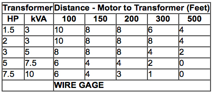
Chart 2 - Three Phase Motors ( 230 & 460 VOLTS )
Speed Electric Drives
Reliable, easy-to-use units are available today for controlling the speed of AC and DC industrial motors. Both types use solid state devices for power control. DC drives are the more straightforward, commonly using silicon controlled rectifiers (SCR's) to convert AC line voltage to controlled DC voltage, which is then applied to the armature of a direct current motor. The more voltage applied to the armature, the faster it will turn. DC drives of this type represent an excellent value for motors up to approximately 3 HP, allowing 60:1 speed regulation and full torque even at reduced speeds. The most common type of AC drive today begins much the same way as a DC drive does - by rectifying "pulsing" AC line voltage to pulse-free DC voltage. However, instead of outputting the DC voltage, the AC drive must re-introduce pulses into the output in order to meet the needs of an AC motor.
This is done using solid-state switches, such as insulated gate bipolar transistors (IGBT's) or gate turn off SCR's (GTO's). The result is a control technique known as pulse width modulation (PWM), perhaps the most highly regarded type of AC drive for many industrial applications. Motor speed varies with the frequency of the pulses introduced into the output voltage.
Pulse width modulated AC drives offer an extremely wide speed range, a host of control functions including programmable acceleration and deceleration ramps and several preset speeds, excellent energy efficiency and, in many cases, speed and torque precision equal to or closely approaching that of a DC system. Perhaps the major reason for their growing popularity; however, is their ability to work with the wide range of AC induction motors available for industry, usually at a price competitive with that of a DC drive package.