

Salt Brine Production System Specs
It is the intent of this Specification to describe in detail an Ultra Easy-Clean Out Brine Production System. This system is designed and constructed to convert rock salt to finished salt brine. It also includes a self-contained hydraulic system to rotate the lower brine holding tank and trash screen down when cleaning is desired, allowing all debris in the salt hopper to simply flow into a standard 2 or 3 cu. yd. loader bucket. Total clean-out will only take approximately 10-15 minutes and requires no personnel entry into the system for shoveling and no "quick attach" loader buckets.
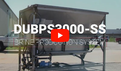
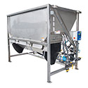 DU BPS3000-SS Salt Brine Production System
  Deicing / Anti-icing Equipment Category
 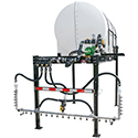 Self-Loading Skid Sprayers for Deicing / Anti-icing
 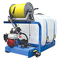 Baseplate & Skid Sprayers for Deicing / Anti-icing
 Salt Brine Maker Breakdown
I. General
- The BPS3000 Brine Production System is capable of producing approximately 3,000 Gallons of Brine Per Hour (based on owner's water supply of 50 GPM or more).
- System is designed and constructed to be easily filled with rock salt using a standard 2 cu. yd. or 3 cu. yd. loader bucket (no conveyors or augers required).
- System is also designed and constructed to be easily cleaned of all debris in the salt hopper with a standard 8' wide 2 cu. yd. or 3 cu. yd. loader bucket (no "quick attach" loader buckets are required). To do this, the loader operator will simply position his loader bucket below the system's lower brine holding tank. He will then switch on the system's self-contained hydraulic control Power Pack. The operator will then rotate the pivoting trash screen and lower brine holding tank down, allowing all debris in the salt hopper to flow into the loader bucket.
- System is designed and constructed to provide for easy clean out of the silt and other fines inside the lower brine holding tank as follows: The operator will again rotate the system's lower brine holding tank down, this time with the pivoting trash screen held in the "up" position. He will then remove the secondary screen inside the lower brine holding tank and wash out the silt and other fines using a standard water spray hose.
- Entire system is constructed on a single skid frame to allow for easy loading, unloading, and moving using various loaders with forks (system can also be lifted into place).
- System is a "downward flow" brinemaker where the salt bed acts as a "filter bed" as the water moves down through the bed from the top spray bars. This provides for cleaner brine (less suspended solids in the finished brine) than upward flow brinemakers produce.
- Overall system dimensions are: 10'9" wide x 6'1" deep x 8'0" high.
II. Upper Salt Hopper
- The Upper Salt Hopper has an approximate capacity of 6-1/4 cubic yards of rock salt. It is 120" (10'0") wide by 63" (5'3") deep at the top to allow for easy loading with rock salt with 2 or 3 cubic yard loader buckets. The back side of the hopper is angled forward (tapered). There are also inward tapers on the left and right sides of the lower portion of the salt hopper.
- The Upper Salt Hopper is constructed of 10 gauge, 304 stainless steel.
III. Pivoting Trash Screen
- A 14 gauge 304 stainless steel trash screen is located at the bottom of the hopper. This screen has approximately 1/4" diameter circular holes through it. The screen is hinged on its back side and has a securing device on its front side so it can rotate down with the Lower Brine Holding Tank, or be secured in the up position for additional cleaning of fines from the Brine Tank.
IV. Lower Brine Holding Tank
- The Lower Brine Holding Tank is constructed of 10 gauge, 304 stainless steel.
- 304 Stainless steel support members runs across the Lower Brine Holding Tank at proper spacing to provide support for the trash screen above.
- A 16 gauge 304 stainless steel secondary screen is located approximately 6-8" from the bottom of the Lower Brine Holding Tank. This screen has approximately 1/8" diameter circular holes through it. The screen is also removable for cleaning purposes.
- A 2" stainless steel female thread bung or coupling is welded into the back side of the Lower Brine Holding Tank.
- The back side of the Lower Brine Holding Tank is hinged and also has locking pins on the left and right front sides so it can rotate down and back up again (for cleaning purposes). The back hinges/sleeves and front locking pins/sleeves are 304 stainless steel. The torsion bar on the back side of the Lower Brine Holding Tank is also 304 stainless steel.
- Lower Brine Holding Tank holds approximately 150 gallons and has a forward taper on its back side. It is approximately 94" (7'10") across its front so a standard 2 cubic yard or 3 cubic yard front end loader bucket can be easily positioned underneath it.
V. Skid Frame
- Skid Frame will support all other system components including the Upper Salt Hopper, Lower Brine Holding Tank, hydraulic system, brine discharge pump, plumbing, and electrical control panel.
- The entire Skid Frame is constructed of structural stainless steel tubing, 3" x 3" x 3/16".
- The Skid Frame has 3" x 3" x 3/16" structural stainless steel bottom cross beams on each side and two across the rear. These cross beams are located approximately 6-8" above the floor to enhance floor cleaning. The Skid Frame also has a 3" x 3" x 3/16" structural stainless steel front cross beam welded to the frame to support the locking pins for the Lower Brine Holding Tank and trash screen.
- Skid Frame also has 3" x 3" x 3/16" structural stainless steel cross beams running across the top on the front, back & both sides. It also has 3" x 3" x 3/16" structural stainless steel beams running diagonally on both sides.
- Each vertical leg of the skid frame shall has a stainless steel base feet (pre-drilled) for securely anchoring the skid frame to the floor.
- Stainless steel lifting lugs are provided on all four corners of the skid frame so an overhead or portable crane can be used for lifting and positioning the system.
- The entire Skid Frame also offers a 3" x 3" x 1/4" carbon steel structural square tubing (Optional Bid Item-DU BPS3000). This carbon steel skid frame will be pre-cleaned with phosphoric acid & steam heat (to "etch" the steel for better paint adhesion), blown dry, and painted with a two-part epoxy primer followed by a two-part urethane top coat.
VI. Hydraulic System
- Hydraulic System for rotating the Lower Brine Holding Tank & trash screen down and up is completely self-contained (no hydraulic lines or connections required by owner).
- The Hydraulic System includes a hydraulic pump with integral reservoir. The hydraulic pump is operated by a close-coupled 1 HP, 220 Volt, 1 Phase, Totally Enclosed (TENV) electric motor (1 HP at 30 minute duty cycle; 2.5 HP at 5 minute duty cycle). The system also includes a pressure relief valve. Two 2-1/2" diameter hydraulic cylinders are also included, sufficient in size to rotate the Lower Brine Holding Tank. The cylinders are securely pinned to the Lower Brine Holding Tank. A hydraulic control valve is also included to retract and extend the hydraulic cylinders. Proper hydraulic tubing and fittings are included to provide a complete & fully operational system. Hydraulic tubing is steel with zinc plating with a 24 hour salt spray rating. Hydraulic fittings are JIC steel fittings with yellow di-chromate finish with a 96 hour salt spray rating.
VII. Brine Discharge Pump
- Pump is a 2" x 1-1/2" straight centrifugal constructed of 316 stainless steel (housing, impeller & mounting feet) with viton/carbon/ceramic mechanical seal. Pump is close-coupled to a 3 HP, 220 Volt, 1 Phase, TEFC motor. Pump is capable of producing a maximum flowrate of 150 GPM and also 80 GPM at 62' total dynamic head (TDH).
VIII. Discharge Plumbing
- Discharge plumbing makes maximum use of polypropylene valves & pipe fittings (with stainless steel suction manifold) for corrosion resistance and quick & easy maintenance.
- Suction plumbing to the Brine Discharge Pump includes a 2" EPDM suction hose (wire reinforced) with a 2" check valve (on the Lower Brine Holding Tank port). It also includes a 2" valve and camlock male adaptor for pulling finished brine from a storage tank hose. Also included is a 3/4" fresh water inlet valve.
- Discharge plumbing from the Brine Discharge Pump includes a 2" valve & camlock male adapter for storage tank hose hook-up. It also includes a 3/4" valve for sampling the finished brine concentration.
IX. Water Inlet & Spray Bar Plumbing
- Water inlet plumbing includes a 2" polypropylene valve (1-1/2" I.D.) with 2" camlock male adaptor for water inlet hose hook-up. It also includes PVC, Schedule 80 piping running through both the front and back sides of the Upper Salt Hopper.
- The water spray pipes (PVC) runs along the entire length of the front and back sides along the top rim of the Upper Salt Hopper. They have drill holes at proper spacing and size to concentrate solid streams of water onto the salt pile in the Upper Salt Hopper.
- Two 1-1/2" polypropylene swivels will be installed in the water inlet plumbing just outside the entry point of the PVC pipes into the Upper Salt Hopper. These swivels will allow the operator (with special tool provided) to rotate the water spray pipes at least 45 degrees while standing on the ground. This will allow for continued concentrating of the solid streams of water onto the salt pile even when the pile height is being reduced (when preparing for clean-out).
- A 2"-24 Volt electric ball valve (1-1/2" I.D.) is included in the water inlet plumbing. This valve will be automatically closed when the float switch in the Upper Salt Hopper or Lower Brine Holding Tank is activated (indicating that the water inflow rate is faster than the brine pump discharge rate, or that it may be "time to clean" the system). An indicator light on the system control panel will also turn on when this water inlet valve is closed to alert the operator to either reduce the water inflow rate, or allow the system to automatically self-regulate if he chooses.
X. System Control Panel
- The System Control Panel includes a NEMA 4X (weathertight) hinged, fiberglass, gasketed enclosure securely mounted to the skid frame.
- Panel also includes a power disconnect switch with lock-out/tag-out, motor control, 220/24 Volt transformer, waterproof switches (wired 24 Volt) including "auto" switch, pump only switch, and hydraulic system switch with indicator lights. Panel also includes an indicating "time to clean" light and an indicating "reduce flow" light. Panel is wired to four float switches: one to shut off the brine pump should the brine level drop too low in the Lower Brine Holding Tank (to protect the pump from running dry), two more to shut off the electric water inlet valve (when water inflow rate is faster than brine pump discharge rate; one in the Lower Brine Holding Tank and one in the Upper Salt Hopper), and one to indicate "time to clean" (in the Upper Salt Hopper).
- Panel is wired with overload protection and ready to receive 220 Volt, 1 Phase power (power supply to panel to be direct wire in proper conduit, by owner's electrician).
- Electrical System also includes flexible conduit with liquid-tight connectors from the Control Panel to the brine discharge pump and hydraulic system pump motor.
XI. Other Safety/Operational Features
- System includes a "Time to Clean" flashing beacon which will be activated by a float switch inside the Upper Salt Hopper. The flashing beacon will activate any time the water level inside the Upper Salt Hopper rises to a pre-determined level, indicating that the system may be ready for cleaning.
- System also includes two round "Sight Windows" in the Upper Salt Hopper. These windows are constructed of Lexan and are positioned so the operator can see the salt level in the Upper Salt Hopper from the floor, once the salt level lowers.
- Both the "Time to Clean" system and the "Sight Windows" provide key safety advantages in addition to operational advantages in that no ladders will be required to check the salt or water level in the Upper Salt Hopper, or to determine when it is "Time to Clean" the system.
- System includes two 14 gauge 304 Stainless Steel Perforated Safety Shields (one on each end of system).
XII. Manuals
- One Installation & Operation Manual shall be supplied with each system delivered (copies available at no additional cost).
- Plumbing & Wiring Schematics shall be included in the manual.
XIII. Warranty
- Warranty will begin at the time system(s) are delivered.
- Warranty will be for one year, including all system components & parts (labor by owner; not included).
- See Owner's Manual for complete safety, operational, and warranty information.
XIV. Optional Items
- A remote stop-start pump switch with 52' SJO cord, SPST rubber boot switch, 24 Volt can be provided at additional cost.
- A complete accessories plumbing kit to connect the Brine Production System to a brine storage tank including 100' of 2" EPDM suction/discharge hose, necessary 2" polypropylene fittings and camlock couplers, one 1" in-line digital flowmeter (for precise measurement when adding water for salinity adjustment), 25' of 3/4" water hose, stainless hose clamps, two 2" stainless steel ball valves and 2" stainless nipples (for the brine storage tank)-DU 1B020 or DU 1B020SS (similar kit with stainless pipe fittings and three 2" x 25' pre-coupled hose assemblies with stainless camlock couplers) can be provided at additional cost. Includes plumbing diagram for quick and easy installation. Other accessory plumbing kits are also available.
- A complete plumbing kit to filter brine on the way to storage (located between the Brine Production System & storage tank) including the following: two 1-1/2" "self-cleaning" line strainers with 100 mesh stainless screens (50 & 80 mesh also available), plumbed in parallel with four 2" polypropylene ball valves, and all necessary 2" polypropylene tees, elbows, nipples and camlock male adaptors (ready to receive 2" camlock coupler hose connections each end)-DU BFS2 (threaded fittings) or DU BFS1 (2" full port flanged fittings). Includes plumbing diagram for quick & easy installation. Optional stainless steel wall mounting bracket is also available.
- On-site training can also be provided at additional cost (phone support during installation and training is provided free of charge).