

Maintaining your RO system properly not only ensures spot-free results in your car wash but also extends the lifespan of your equipment. One of the most important aspects is replacing the RO membrane. This guide will cover how often you should change your RO membranes, what signs indicate it’s time for a replacement, and the tools and equipment you’ll need to perform this task effectively. Let’s dive in.
Understanding RO Membranes and Their Importance
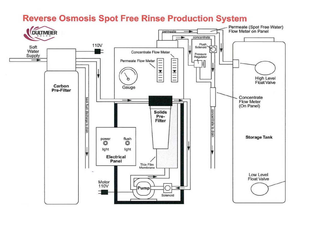
An RO membrane is a core component of your RO system, responsible for filtering out dissolved solids, contaminants, and other impurities from the water. Over time, the membrane's ability to filter water diminishes due to several factors, primarily scaling and general wear and tear, making regular replacement necessary to maintain optimal water quality.
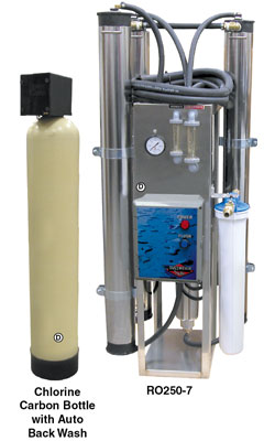
Chlorine filters are essential to prevent chlorine from entering the membranes, as chlorine will cause rapid damage and failure. Additionally, a water softener is typically required to reduce water hardness to zero before it enters the membranes. When newly installed, the membranes take TDS down to zero.
How Often Should You Change Your RO Membranes?
Generally, RO membranes can last up to about 1 to 5 years, but the exact lifespan depends more on system usage and water quality than on time alone. Rather than focusing on a specific timeframe, it’s best to monitor the Total Dissolved Solids (TDS) level in the water your system produces. When TDS levels start to rise, it indicates that the membrane is less effective and may need replacing. This approach helps you avoid unnecessary changes while ensuring optimal water quality.
Here are some key considerations to help you determine the optimal time to replace your membranes:
Water Quality and Pre-Treatment
- The quality of your incoming water greatly affects the lifespan of the membrane. High levels of water hardness, iron, or chlorine will greatly affect membrane life. If your water supply has high levels of these contaminants, you will likely need to replace membranes more frequently.
- Pre-treatment options, such as sediment filters, carbon filters, and water softeners are very important for extending membrane life by reducing the burden on the RO membrane.
You can contact our sales team for help selecting pre-treatment options.
System Usage
- The more frequently your RO system is used, the faster the membrane will become filled with contaminants, and performance will go down. For car wash operations with heavy daily usage, you may need to replace the membrane more frequently.
- In contrast, for systems used less frequently or with lower output, a membrane will last much longer.
Regular Monitoring and Maintenance
Performing weekly TDS checks is a key to monitoring the condition of your RO membrane. A handheld TDS meter can help you measure the TDS levels in the permeate (filtered water). If TDS readings exceed 40 ppm, it’s time to replace the membrane, as spotting generally occurs at this reading and above.
Regular maintenance and monitoring can help catch issues early, preventing costly replacements and downtime. Cleaning the inlet filter and solenoid can prevent strain on the membrane. Your water softener should also be backflushed periodically. Many systems have an automatic backflush feature that cleans the filter media by flushing out accumulated contaminants, dirt, and debris, helping maintain the filter’s efficiency and lifespan.
Testing the TDS with a Handheld Meter
Step-by-Step Instructions for Testing TDS with a Handheld Meter
- Prepare a Clean Sample Container:
- Collect a cup or use the cap of the meter to hold your water sample.
- Rinse the container thoroughly to ensure it is free of any contaminants.
- Collect the Water Sample:
- Use the container to collect a sample of the permeate (filtered water) from your RO (Reverse Osmosis) system.
- Turn on the TDS Meter:
- Remove the cap from the TDS meter.
- Press the ON button to activate the meter.
- Insert the Meter into the Sample:
- Place the TDS meter into the water sample up to the “ribbed” section on the meter for an accurate test (see image below).
- Swirl the Meter:
- Gently swirl the TDS meter in the water for about 10 seconds to ensure the water flows consistently around the sensor.
- Hold the Reading:
- Press the HOLD button on the meter to lock in the reading. This will allow you to remove the meter from the water without losing the result.
- Read and Record the TDS Level:
- Check the TDS level displayed on the screen in parts per million (ppm).
- The meter will hold this reading for approximately 20 seconds, giving you time to record the result.

Dultmeier Item #HMTDS4
Signs It’s Time to Replace Your RO Membrane
Apart from monitoring TDS, there are additional signs that indicate it may be time for a new membrane:
- High TDS Levels: If TDS readings start to increase rapidly or are above 40 ppm despite cleaning or flushing the system, this is a clear indicator that the membrane is no longer effective.
- Decreased Water Production: A significant reduction in the system’s output or water flow could mean that the membrane is fouling or needing service.
- Visible Spotting on Vehicles: For car wash systems, if you notice water spots on vehicles after washing, this suggests that the membrane isn't producing spot-free water.
- Increased RO System Noise: An underperforming pump or noisy operation could indicate that the membrane is placing too much strain on the system.
RO systems are complex and you can find more details in our guide to RO system troubleshooting.
Recommended Tools and Equipment for RO System Maintenance
To keep your RO system running smoothly, equip yourself with the following tools and replacement parts:
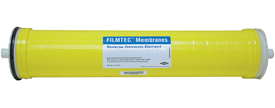
Replacement RO Membranes
Choose the right membrane based on your system’s specifications. Dultmeier offers a selection of RO membranes from several different manufacturers and systems.
TDS Meters
Handheld TDS meters are essential for regular monitoring. You can use these to quickly check if your membrane is maintaining water at the appropriate quality standards.
Pre-Treatment Filters
- Sediment Filters: Protect the membrane from debris and particles.
- Carbon Filters: Remove chlorine and organic compounds that can damage the membrane.
- Water Softeners: Prevent hard water scaling, extending membrane life.
Best Practices for Extending RO Membrane Life
Perform Regular Maintenance
Schedule routine checks on the prefilter, membrane, pump, softener, and carbon bottle. Replacing prefilters regularly will reduce the load on the membrane, ensuring it lasts longer.
Flush the System Periodically
Run a flush cycle to remove accumulated debris and scale from the membrane. This should be done according to your system's maintenance schedule or as needed based on water quality.
Dultmeier offers RO systems with automatic flush mode, you can learn more about these systems here.
Invest in High-Quality Pre-Treatment Solutions
Adding carbon filters, sediment filters, or water softeners will help protect your membrane from harmful contaminants and extend its service life.
Monitor Water Quality Weekly
Using TDS meters for regular monitoring helps you detect when the membrane begins to deteriorate. By staying ahead of TDS increases, you can replace the membrane before it causes major issues.
Conclusion
Changing your RO membrane every 1 to 5 years is a general guideline, but regular monitoring and maintenance play a critical role in determining the actual replacement schedule. By keeping a close eye on TDS levels, addressing any performance drops, and using quality replacement parts and pre-treatment equipment, you can maximize the efficiency and lifespan of your RO system.