

Imagine being able to spray a large pasture and doing it without a large and cumbersome boom. With a boomless sprayer, you can do just that!
With no boom to negotiate around obstacles, a boomless sprayer is a convenient way to cover large areas. However, it is not suited for every type of application. Today we're going to break down the ins and outs of boomless sprayers. We will explain specifically what they are, how they operate, and when you should use them.
What is a Boomless Sprayer?
A "boomless" sprayer is designed to distribute liquids, such as herbicides, pesticides, and fertilizers, without the traditional long, horizontal boom. Instead, these sprayers use specialized nozzles to achieve wide coverage without the extensive boom. This offers several advantages.
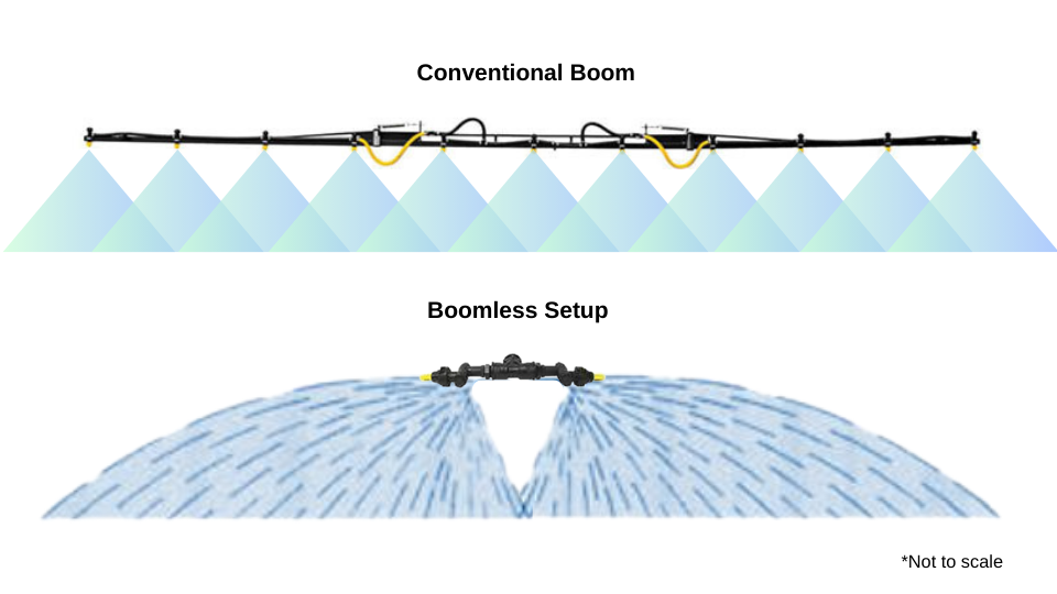
A conventional sprayer boom has long arms extending from the sides of a sprayer that hold several nozzles at set intervals, providing a uniform application over a wide swath. In contrast, boomless sprayers use one or more "boomless" nozzles that are mounted at the rear of a sprayer. These nozzles can cover a similar span in one pass as a conventional boom.
Conventional Boom vs Boomless Setup:
Common Applications of a Boomless Sprayer
Boomless sprayers have gained popularity due to their unique advantages over conventional boom sprayers. They are particularly useful in areas with obstacles, uneven terrain, or narrow paths where maneuverability and flexibility are crucial. The absence of a boom reduces the risk of damage to equipment and surrounding fences, buildings, etc. This makes boomless sprayers a practical choice for farmers, ranchers, turf care pros, and property managers.
Boomless sprayers can be used for several applications:
- Pasture spraying: Ranchers can spray areas of their pastures that are hard to access with a large spray boom. It allows you to spray steep hillsides, ravines, and fence lines.
- Landscaping: Landscapers benefit from the flexibility of boomless sprayers when maintaining large lawns, parks, and golf courses. Without a boom, it is much easier to navigate around trees, bushes, and other landscape features making it an efficient tool for maintaining green spaces.
- Forestry: In forestry management, boomless sprayers are employed to apply treatments over large, wooded areas. Their ability to cover wide swathes of land quickly and effectively helps in pest control and vegetation management.
- Golf Course: Spraying Greens from the fringe.
- Municipal and Public Works: Municipal workers use boomless sprayers for tasks such as roadside weed control and maintaining public parks. The ease of use and wide coverage make them suitable for maintaining large public spaces.
- Food Plots: Many boomless sprayers can fit on ATVs and UTVs making them perfect for spraying remote food plots for wild game.
- Boom Extending: Used as the last nozzle on a conventional boom to extend reach, spray fence lines, waterways, etc.
This video demonstrates what a boomless nozzle looks like in action on the end of a sprayer boom:
You can check out the details of the boomless nozzle control kit referenced in the video here: KZ Boomless Nozzle/Valve Control Kit
How Does a Boomless Nozzle Work?
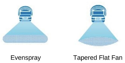
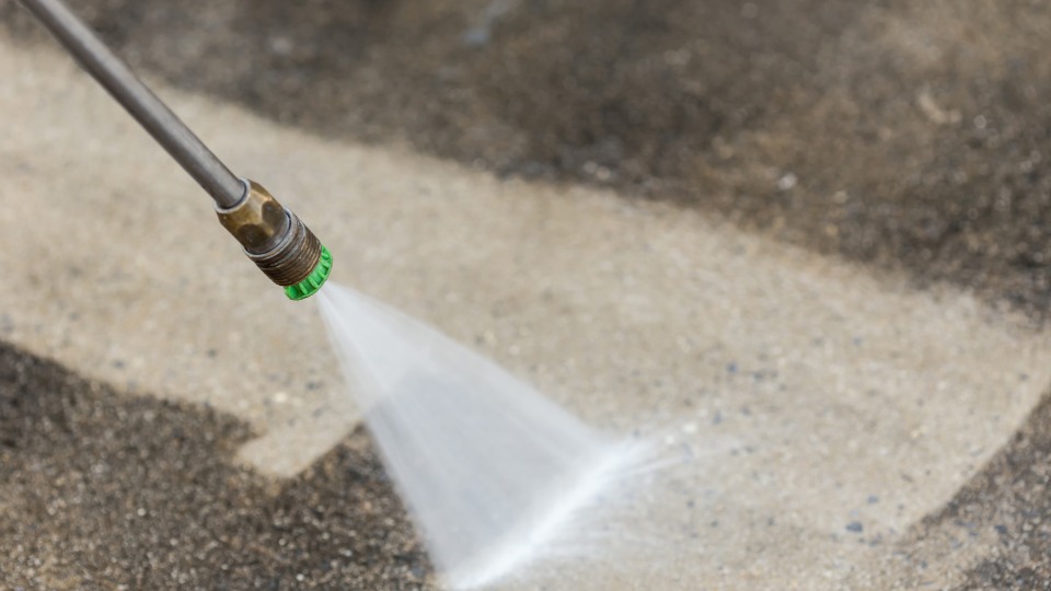
A boomless nozzle has a unique design that projects fluid over a wide area. Inside the nozzle housing, a vane or diffuser breaks up the stream of fluid so that droplets are formed across the entire width of the spray pattern.
With a typical spray nozzle that projects fluid over a great distance, the stream stays together as it travels through the air-only dispersing into droplets in an isolated area. A boomless nozzle both projects fluid over a great distance but also provides coverage of the surface along the entire swath.
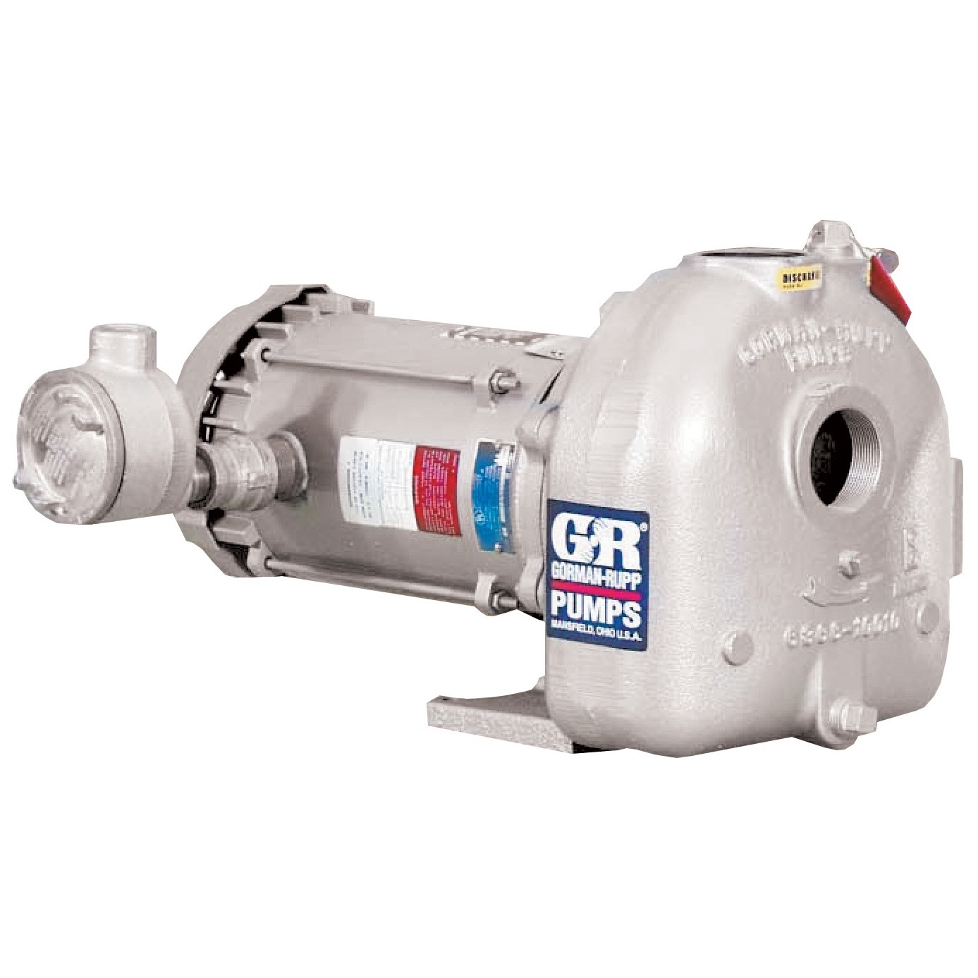
The design is rather ingenious and the only difference between a traditional boom sprayer and a boomless sprayer is the lack of a boom. In terms of the tank, pump, and controls, you can design and operate a boomless sprayer basically the same as other sprayer types.
Pros and Cons of a Boomless Sprayer
While a boomless sprayer is very effective in the right application, there are specific scenarios where it is not the best option.
Due to the high-volume, wide-angle spray pattern, a boomless sprayer nozzle produces very coarse droplets. While these coarse droplets are less prone to drift, they do not offer the same consistent coverage as a conventional boom.
Boom Sprayers
Pros:
- Precise and uniform application
- Suitable for large, open fields
- Consistent spray pattern and coverage
Cons:
- Difficult to maneuver in tight or obstructed areas
- Risk of boom damage from obstacles
- Requires more careful navigation and operation
Boomless Sprayers
Pros:
- Flexible and versatile coverage
- Easy to maneuver in irregular and obstacle-rich areas
- Reduced risk of equipment damage
Cons:
- Potential for less uniform coverage compared to boom sprayers
- The spray pattern may need adjustment for different applications
- May not be as effective in large, open fields where precision is critical
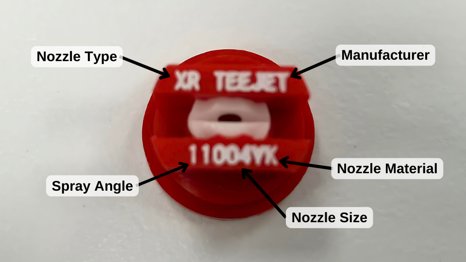
Boomless Nozzle Types
There are several different manufacturers of boomless sprayer nozzles. While they do vary in design and exact specifications, the basic premise is the same. They are available in stainless steel or poly material. Boomless nozzles range in both the volume of liquid they will deliver and the width of the spray pattern they produce. There are small nozzles that spray a 3-5 ft pattern up to larger nozzles that will cover nearly 40 ft in one direction.
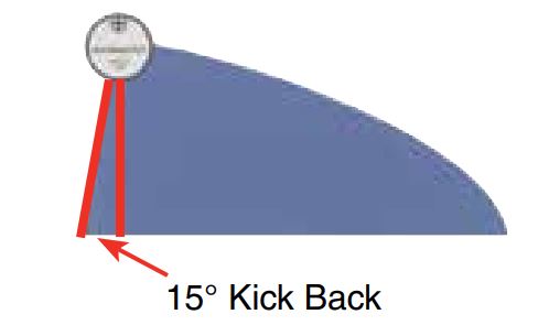
Generally, a boomless sprayer will consist of two boomless nozzles installed "back-to-back" on a sprayer about 6 inches apart depending on the exact nozzle. The standard boomlesss nozzles have a slight "kickback" so they overlap when mounted in this manner.
This is the nozzle you would use on the back of a sprayer in place of a conventional boom. With each nozzle acting as half of the sprayer swath. You can control these nozzles individually, giving you the ability to control whether you spray to the left, right, or full pattern.
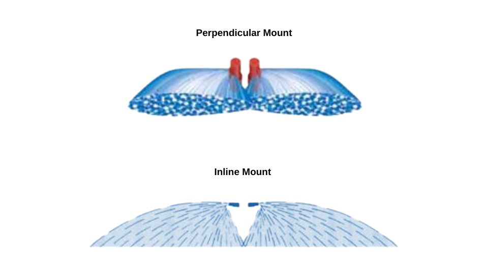
There are two varieties of this nozzle. They perform the same the only difference is in the direction of spray in relation to the inlet port. Most of these nozzles have an NPT inlet and the outlet is either opposite this inlet or perpendicular.
There are also boomless nozzles that will cover a full swath with one spray nozzle. These full-pattern nozzles are offered by Boominator and Teejet.

Full pattern boomless nozzle.
TeeJet also offers a BoomJet boomless assembly that consists of multiple nozzles mounted on one body. Together they can cover a wide area with even coverage
Finally, we have the popular roadside or right-of-way boomless nozzle. This nozzle is similar to the standard types; however, it has a significant distinction. Roadside nozzles do not have a "kickback" to their pattern. These nozzles are not intended to overlap with another nozzle. Instead, they are mounted on the side of a truck or other vehicle to spray road ditches, medians, or any area adjacent to the vehicle. With no "kickback", there is no liquid sprayed on the vehicle.

The roadside nozzle pattern does not feature a kickback for overlap
How to Mount Boomless Nozzles
No matter what type of boomless nozzles you use, it is crucial to mount them correctly. Incorrect mounting can limit your coverage and lead to poor results. Here are the basic guidelines to follow when you mount different types of boomless nozzles:
Boomless Nozzle Height
The vast majority of boomless nozzles are intended to be mounted and used at a height of 36 inches from the ground. Most will perform at a minimum height of 18 inches from the ground and a maximum of about 48 inches. Changing the height does result in slightly narrower or wider coverage.
There are boomless nozzles that can be mounted lower than 18 inches off the ground. Boominator short pattern nozzles cover a narrower spray distance of about 3-10 ft. You can mount them 12 inches from the ground.
Boomless Nozzle Spacing
A pair of boomless nozzles on a sprayer should be mounted about four inches apart. This ensures an overlap between them. Nozzles mounted higher than 36 inches may adequately overlap at 6 inches or more, but the nozzle angle may need to be adjusted up or down.
Boomless Nozzle Plumbing
Boomless nozzles deliver more fluid per minute than flat fan nozzles on a spray boom, so they require an adequately sized hose to feed them. If you are using a single nozzle, it is best to use a hose or pipe with an inside diameter larger than the nozzle inlet. If you are feeding two nozzles, then the hose should be double the inlet size of the nozzle inlet. This is especially important if you have a long length of hose between the pump and the nozzles.
You can refer to the manufacturer's website for more specific boomless nozzle plumbing and installation instructions:
Boomless Sprayer FAQ
Question: What is the farthest a boomless nozzle can spray?
The widest swath you can cover with a boomless sprayer would require using two standard Boom Buster 504 nozzles. Each one can spray about 40 feet in one direction. With two of these mounted "back-to-back", you could potentially spray a width of 80 ft.
Question: Can I add a boomless nozzle to my sprayer?
Yes, a boomless nozzle can be added to basically any sprayer type. It is important to make sure your sprayer has a pump large enough to provide the flow needed for the nozzles you choose.
Question: Do Boomless Sprayers Work Well?
A boomless sprayer works extremely well in the right scenario. They produce coarse droplets that are less prone to drift and are perfect for fertilizers, orchard spraying, de-ice, pasture spraying, and much more. They excel in areas with obstacles.
They are less suited for applying herbicides that require thorough coverage of the target surface. If you need nozzles that produce finer droplets see our selection of flat fan sprayer nozzles.
Question: How much volume can a boomless nozzle spray?
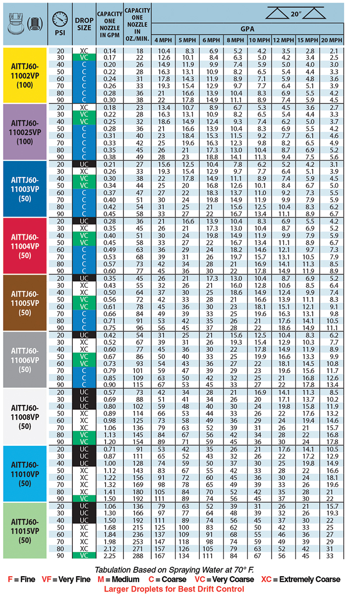
Boomless nozzles come in various sizes. The smaller nozzles can produce a flow of about 1-2 gallons per minute. At 2 GPM and a 30-foot spray width, this amounts to about 12-13 gallons per acre at 5 mph.
You can pinpoint the exact gallon per acre rate at different speeds in the boomless nozzle chart for each type.
Boomless Nozzles Options
There are quite a few options and the distinctions between them may seem arbitrary so here are the options we carry and some of the key benefits of each type.
TeeJet
- BoomJet - Solid brass unit that is very durable and provides even coverage.
- XP Boomjet - A cost-effective poly nozzle that is lightweight and easily added to Teejet Quickjet nozzle bodies with a Teejet 1/4 cap.
Boominator
Boominator nozzles provide several different patterns that are made of durable stainless steel:
Boom Buster
Unlike other types of boomless nozzles, Boom Buster nozzles do not have a "left" and "right" hand version. Any two nozzles can be used in tandem to create a full pattern.
Hypro
- Boom X Tender - These can be rebuilt with a repair kit.
- Fast Cap Boom X Tender - Same as the standard X Tender nozzles but they fit on Teejet and Hypro quick jet nozzle bodies.
Boomless Nozzle Accessories
- Boomless Nozzle Swivel Tee - Simple kit mount boomless nozzles
- Golf Course Boomless Green Sprayer - Solenoid control and mounting kit for golf course sprayer booms, can be used on other sprayer types.
We have several of these in stock and we can ship them out the same day you order. Do not hesitate to get in touch with us if you need any help choosing the right boomless nozzle for your sprayer.

Tech Ag & Industrial Sales
Shane Blomendahl is a tech sales veteran at Dultmeier Sales with over 10+ years of experience in liquid handling products covering several industries and applications.


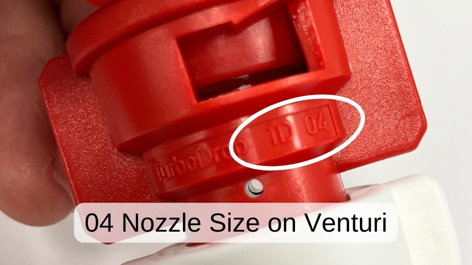
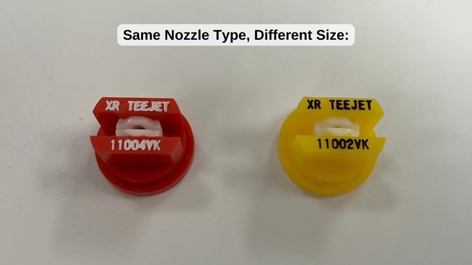 The red nozzle is an 04 size and the yellow nozzle is an 02 nozzle.