

We speak a lot about sanitation and disinfection these days. From the office and classroom to our own personal spaces, we are focused on cleaner, safer areas more than ever. And while many businesses are just now taking a closer look at how they clean their facilities, disinfecting in food processing has long been serious business. That doesn't mean all disinfectants for food processing cleaning are made equal.
Disinfectants come in a variety of forms, each with its distinct advantages and disadvantages. In fact, which disinfectant you choose for your application is just as important as the why and how you disinfect. As we'll cover in this article, understanding the basics of each disinfectant type and the general rules behind applying them ensures a more comprehensive and cost-effective cleaning regimen. Read on for our breakdown of disinfection basics for more effective disinfecting.
Contents
Why Disinfecting in Food Processing is So Important
Choosing the Right Disinfectant for the Environment & Application
Disinfectant Type Comparison: Foam, Spray & Steam
Disinfecting Scope-Know Before You Go
Safety First: Personal Protective Equipment (PPE) for Disinfecting
Why Disinfecting in Food Processing is So Important
While commercial processing facilities spend the majority of their time up and running, their most important activity occurs when the production floor is empty and silent. Maintaining clean, sanitary workstations and equipment, particularly in food processing, is integral to public health and safety. In the United States, such standards are overseen by government agencies such as the EPA, CDC, and USDA.
But why disinfect at all?
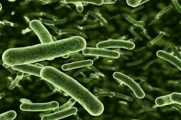
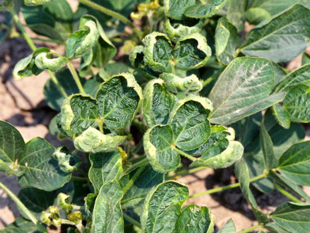
E. coli, a common bacterial target of disinfecting food processing facilities
Well, for starters, food processing plants are not the cleanest places once production gets going. Soils, in the form of fats, oils, blood, and other animal protein and production byproducts, quickly collect on equipment and surrounding surfaces. Such deposits, if left unaddressed, make these surface areas ideal breeding grounds for countless hosts of bacteria, viruses, and other potentially harmful microorganisms.
Proper cleaning removes these unwanted soils and contaminants, providing significant benefits downstream. Maximized production efficiency, increased product shelf life, safer work conditions, and fewer mechanical failures and delays are but a few positive outcomes to attentive housekeeping. Scheduled cleaning and disinfection also significantly decrease the chances of costly product recalls due to food hazard risks such as food poisoning or foreign body contamination.
A processing plant's commitment to a culture of health and food safety can easily be seen by how devoutly they approach the cleaning and disinfecting processes. And yes, there is a difference between the two.
Cleaning vs. Disinfecting
For most of us, cleaning, sanitizing, and disinfecting are all one and the same concept. They are, however, three distinct steps within the larger cleaning process. Cleaning is the process of physically removing unwanted substances and contaminants from a given surface. The cleaning stage, sometimes referred to as the detergent stage, is often characterized by the removal of common soils such as dirt, grease, or oils via manual scrubbing with brushes or wipes or washing with a high-pressure spray wand. Cleaning a surface in this manner alone; however, will not kill germs present.
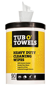
Heavy Duty Cleaning Wipes for removing difficult soils
Disinfecting on the other hand, does kill bacteria and other microorganisms left behind following the cleaning stage. While similar to sanitizing agents, which merely reduce the number of bacteria and other germs to acceptable levels of health safety, surface disinfectants make a surface truly contaminant-free. Their high bactericide concentrations of chlorine or bleach eliminates the ideal growing conditions bacteria and other microorganisms thrive on.
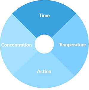
Every cleaning application will follow a distinct set of variables, generally known as TACT. The four aspects of this cleaning/disinfection concept are time, temperature, action, and concentration. How prominently each phase is in the disinfecting cycle depends specifically upon your unique needs, including the soils you're wanting to destroy, and the chemicals being used. Followed properly, the combination of them all will achieve the desired result of a clean, disinfected space.
It's important to understand that cleaning must take place before the disinfecting stage. Since disinfectants do not break through heavy soils on surfaces, removing such deposits ahead of time ensures the disinfectants are able to work with the greatest efficacy.
Choosing the Right Disinfectant for the Environment & Application
Today, disinfectants cover a wide spectrum of chemical concentrations and applications. Choosing the right disinfectant for a specific environment, therefore, can be a task in and of itself. A few things to consider.
First, the choice of disinfectants depends foremost on a user's requirements. In other words, where are they disinfecting and what type of contaminants are they trying to eliminate. After that, the type of processing and cleaning equipment used, the application method, and, to some degree, the personal preference of the user all play a role in selecting a disinfectant.
Also, review a disinfectant's toxicity, leftover residues, and any possible chemical reactions related to water hardness and various surface types. This is particularly important within the food processing industry. Any residual chemical compounds left behind after disinfecting can adversely affect product taste, curing, and shelf life. In the brewing industry, for example, certain disinfectant cleaners are avoided because they linger on glass surfaces. (Soapy beer anyone?) Understanding a disinfectant's proper application process and any residue properties it has helps prevent product quality from suffering.
Once a disinfectant is chosen, the most important thing to remember is to always read your disinfectant product labels! Always. With effective cleaning practices, disinfectants will kill 100% of germs listed by the label-when used properly.
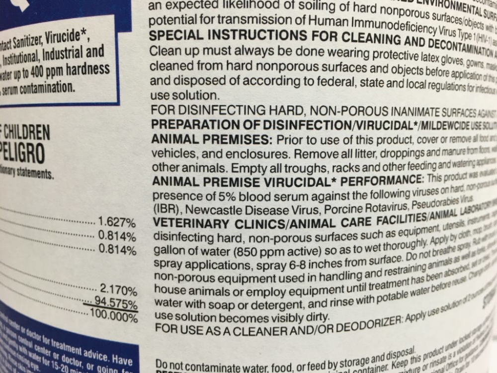
Ignoring what's detailed on the label-or choosing not to read it altogether-is a great way to undermine a disinfectant's effectiveness and cause mechanical failure of your disinfecting systems. It's also quite dangerous. Later in this article, we'll cover some of the safety considerations and equipment needed when dealing with disinfectants. For now, just remember that the label is the law. By following the label, you keep you, your cleaning staff, and anyone who comes in contact with the disinfected area, directly or indirectly, safe.
Disinfectant Type Comparison: Foam, Spray & Steam
Most of the food processing industry today relies on three common disinfectant application types: foam, spray (aerosol), and steam. Since no two environments are exactly alike, no two disinfectants will perform equally across the board either. Below we've provided some comparisons for these three disinfectant types and some general considerations to have before choosing the right disinfectant for your situation.
Foam Disinfectants
Pros:
- Better coverage of surfaces
- Greater visibility of coverage
- Lower pressure application
- Less product needed to work
- More cost-effective than other disinfectants
Cons:
- More challenging mix ratios
- Added costs if needing separate surfactant agent
- Greater attention to spray nozzle orifice size
- Greater flow needed to apply
Foam disinfectants are quite common in most food processing and industrial operations. Why? For starters, foam disinfectants can offer up to 50% more coverage than sprays. This is because foam expands as it comes in contact with a surface, greatly increasing coverage and disinfecting performance. In large production spaces, such as production floors or livestock barns, this helps keep cleaning costs down. Users can realize up to 50% cost savings on chemical alone, with additional savings possible in application time as well. Foaming is also a great option for disinfecting ceilings and vertical surfaces since the foam adheres better than sprays and therefore extends disinfection dwell time.
One challenge with foam disinfectants, however, is the need to include a surfactant. A surfactant is a foaming agent that chemically reacts with your disinfectant chemicals. Surfactants also lower the surface tension between two materials, such as water and dirt, making the soil easier to remove. Without a surfactant, your disinfecting solution will not foam properly, making it less effective. While some disinfectants include a surfactant already, most do not. Be sure to read your labels prior to starting your cleaning process to ensure proper solution effectiveness.
Additionally, check that your application equipment is compatible with foam solutions. Using a high-pressure pump without the appropriate chemically compatible elastomers is a great way to ruin an expensive pump. It is imperative, therefore, to check the chemical compatibility of ALL components throughout your entire cleaning systems. That includes examining the largest pump to the tiniest o-ring. In doing so, you not only avoid costly equipment damages or failures, but also prevent ineffective treatment from taking place.
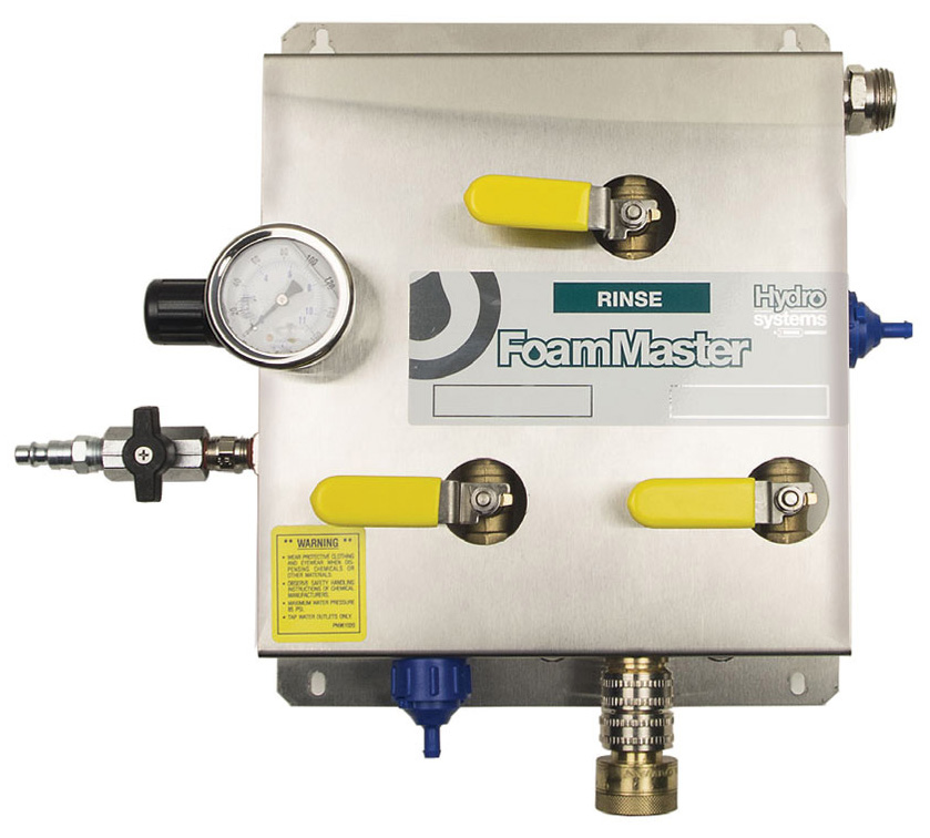
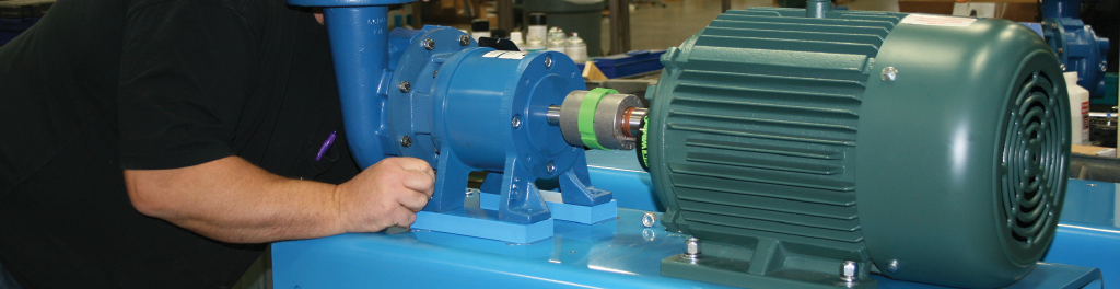
Opt for chemical spray foamers and accessories that feature downstream injectors that bypass incompatible seals and components. Better still, invest in a complete foaming system like the Hydro FoamMaster. Available in multiple mounting styles, the FoamMaster is ideal for larger industrial cleaning applications, from washdown facilities and meatpacking plants to animal production buildings, such as the dairy barns shown in the video above. These compressed air units allow a user to set the desired dilution rate for their specific application. From there, the system mixes the chemical and surfactant with the carrier agent (generally water) to create rich, clinging foam.
Dultmeier has even helped develop custom disinfecting systems. Check out our work on the JBI Poultry Disinfectant Foaming Trailer here.
Spray Disinfectants
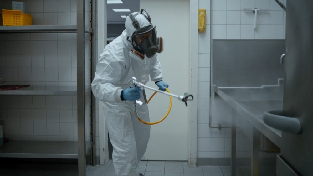
User disinfecting with spray in an industrial kitchen
Pros:
- Fewer chemical compatibility issues
- Quick-and-easy to apply
- Wide variety of disinfectant types
- Usable for almost any application/environment
Cons:
- More chemical usage to achieve adequate coverage
- Generally higher pressures applications
- Greater health concerns due to aerosol emissions
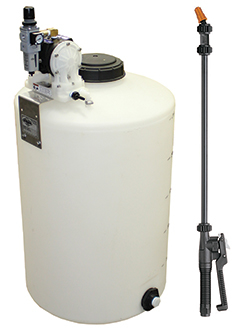
Dultmeier's DC1 Air-Driven Disinfectant Applicator
Aerosols are the most widely used disinfectants used for industrial cleaning tanks to their incredible versatility and ease-of-application. You can find disinfectant sprays for nearly every circumstance and apply them using a commercial pressure washer, handheld or backpack sprayer, or similar system without any chemical compatibility issues. Dultmeier's DC1 disinfectant applicator system, for instance, features an air-powered diaphragm pump, a 25 gallon storage tank with an automatic mixing valve, and a trigger spray wand that can easily store and apply most disinfectant products without a problem.
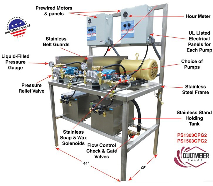
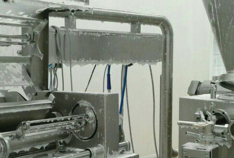
Complete Plant Washdown/Industrial Clean System
The thing about spray disinfectants is that they can be costly. For one, most disinfectant sprays require a high-pressure system to be applied well. These systems; while effective, can be expensive to fund. Furthermore, since so much energy goes into turning a disinfecting solution into spray, an operator may have to use more product to disinfect an area compared to if he used foam.
Steam Disinfectants
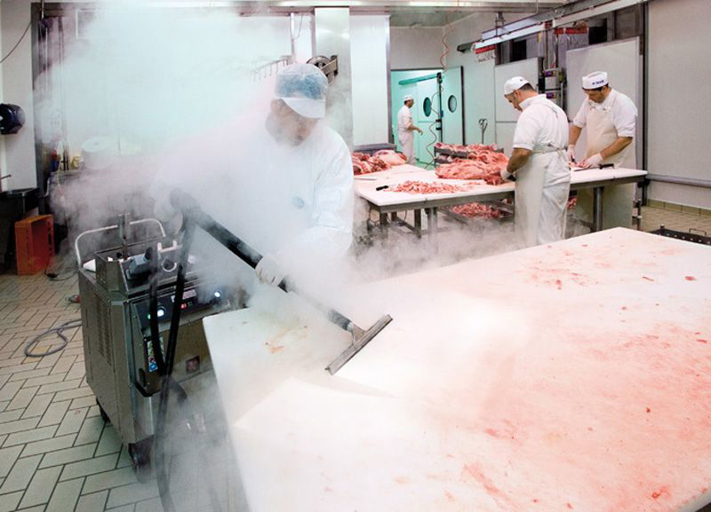
Dry steam disinfecting for food processing sanitation
Pros:
- Effective against a wide range of microorganisms
- Not affected by soils or hard water
- Non-corrosive or chemically reactive
- Leaves behind zero residue
Cons:
- Cannot be used on heat-sensitive equipment or surfaces
- Does not remove large soil deposits
- Dangerous high temperatures to human contact
- Difficult to maintain consistent temperature and exposure
As their name suggests, steam disinfectants work using steam to kill bacteria, spores, and other contaminants. The prolonged exposure to the moist high heat destroys microorganisms, leaving surfaces truly decontaminated.
Although a viable disinfectant method, we recommend using either foam or spray detergents for most applications. The main drawback to steam is that high temperatures, generally either 250° F or 270° F (or greater), must be maintained throughout the disinfection process to ensure microbial death. Such high temperatures can also damage certain components and surfaces. Foams and sprays have much wider applications, which simply makes them better and more-cost effective options for most operations.
Disinfecting Scope - Know Before You Go
No two areas are created equal when it comes to cleaning and disinfecting. Case in point, you don't clean and disinfect an office space in the same way you do a meat packing processing floor. That makes understanding your scope of disinfection all the more important before ever beginning the cleaning process.
Product Needs
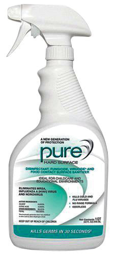
Purehard surface disinfectant; ideal for food processing & food preparation
For instance, the size of the area you're disinfecting will greatly influence the amount of product needed. Do you need a 5-gallon bucket of disinfectant or a 55-gallon drum? Maybe you need more. This is where foam disinfectants really have the advantage. Their enhanced coverage and prolonged contact time with the applied surface allow less product usage.
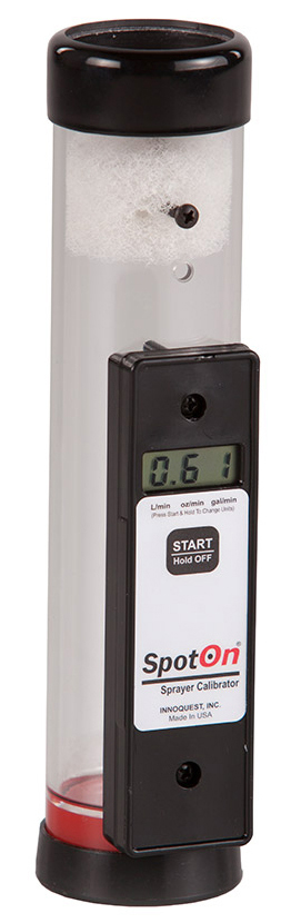
Make note of the GPM flow of your system. If you have a pump that produces 3 GPM of flow attached to a 50 gallon tank, you effectively have 16.5 minutes of continuous application time. Time is money, so how much time will be spent mixing solution is an extremely important thing to remember when disinfecting large areas.
Disinfectant Systems
Your style of disinfectant system is something else to keep in mind. Most operations have some level of clean-in-place (CIP) process. However; for a vast majority of the disinfecting process, mobile cleaning units are necessary to leave an area truly decontaminated. Portable disinfectant systems equipped with powerful pumps and spray wands allow an operator to spray disinfectant at a variety of angles, speeds, and tailored quantities. This versatility ensures every hard-to-clean space can be adequately decontaminated.
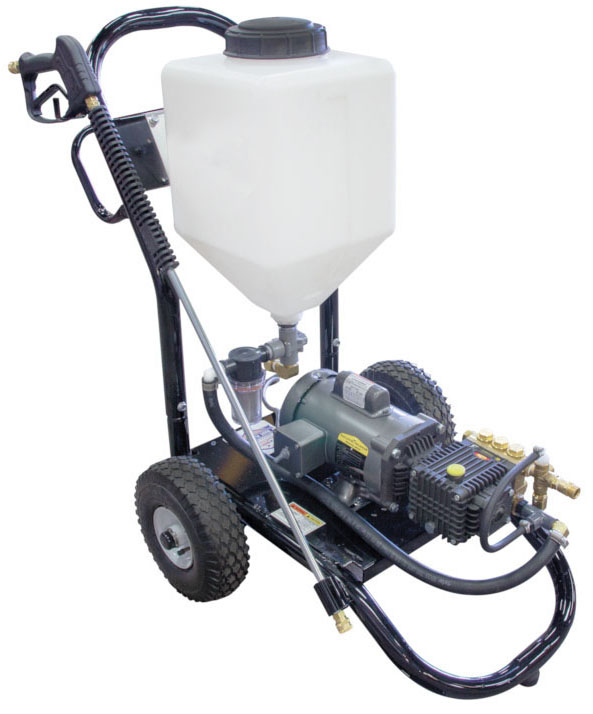
Portable Sani-Mister disinfectant unit
Ventilation
Finally, take a minute to evaluate your space's ventilation. Taking the office vs. processing floor scenario, ventilation is likely very different between the two spaces. On the processing floor, the larger area means aerosols and vapors have more room to dissipate or be dispersed by exhaust fans. In the smaller office space, however, chemical fumes become more of a hazard. Respirator masks may be required based upon the chemicals used and/or size and ventilation capabilities of the application area.
Always be cognizant of how to enter a space for disinfection and understand how your solutions react when in use. Evaluating how to approach an enclosed space for disinfecting and how long someone should be exposed to that environment once they start keeps everyone healthy and safe.
Safety First: Personal Protective Equipment (PPE) for Disinfecting
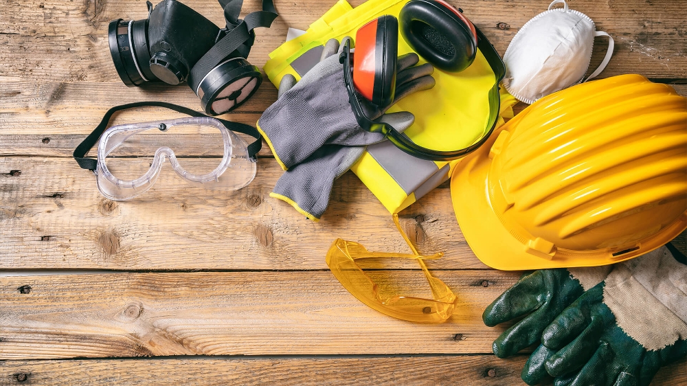
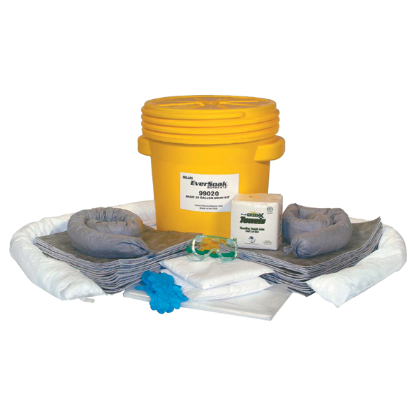
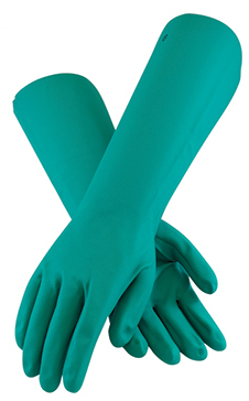
Regardless of the style of disinfecting you ultimately use, you need to wear personal protective equipment, also known as PPE. This protective equipment ranges from nitrile chemical gloves and safety goggles to full body TYVEK coveralls. These products protect you from spills, splashes, and unexpected contact with the disinfectants which can cause serious chemical burns.
Certain aerosol disinfectants may even require a respirator mask to protect you from harmful chemical vapors. Even if the disinfectant label doesn't list a respirator as required PPE, you may still choose to wear one if working in a small, poorly ventilated space. Each chemical application is different.
Read your product labels for the proper PPE required to handle specific disinfectants safely. Regularly inspect PPE for wear or damages and replace if needed. Also, ensure your facility has clearly marked eyewash stations and safety showers in case of an emergency. Whether you need gloves, eye protection, or water-resistant clothing, we can help you find the gear you need to be best equipped for the tasks at hand.
Conclusion
Proper cleaning and disinfecting procedures will always be a serious focus in the industrial and food processing industries. In fact, one of the most important activities that occurs in any industrial processing facility is their disinfectant regimen. Even so, disinfection practices and policies will continue to change with new health research, product development, and societal perceptions. With that in mind, having a reliable, knowledgeable company you can trust to support you is imperative to your business's success.
Dultmeier is that company you can trust. We carry an extensive catalog of disinfectants, personal protective gear, and cleaning equipment and supplies from trusted brands like Mosmatic, DEMA, Suttner, General Pump, Hydro Systems, Boss, and others. While we cannot ultimately tell you how to disinfect, we can share with you the many different methods and assist your operation regardless of your choice of application. We'll happily help answer all your questions about various disinfecting types and work to get you the equipment and products you need to ensure your workspaces are cleaner than ever.
Reach us at dultmeier.com or give us a call at 888-667-5054. Your Experts in Delivering Fluid Handling Solutions - WE KNOW FLOW!


